γ線分光計のフルカラーLEDリボン連携♪
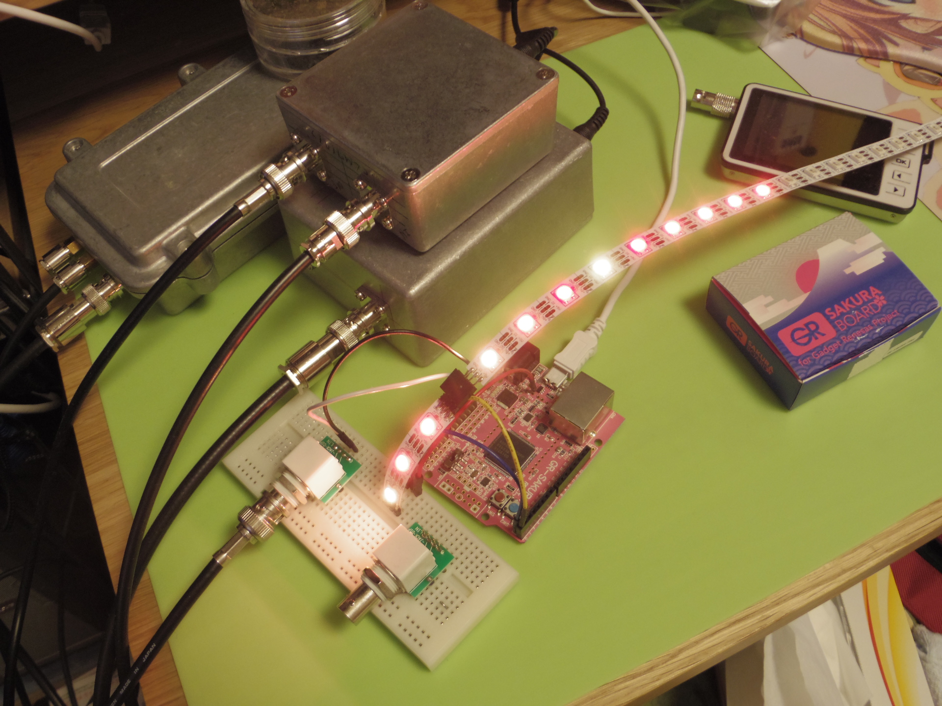
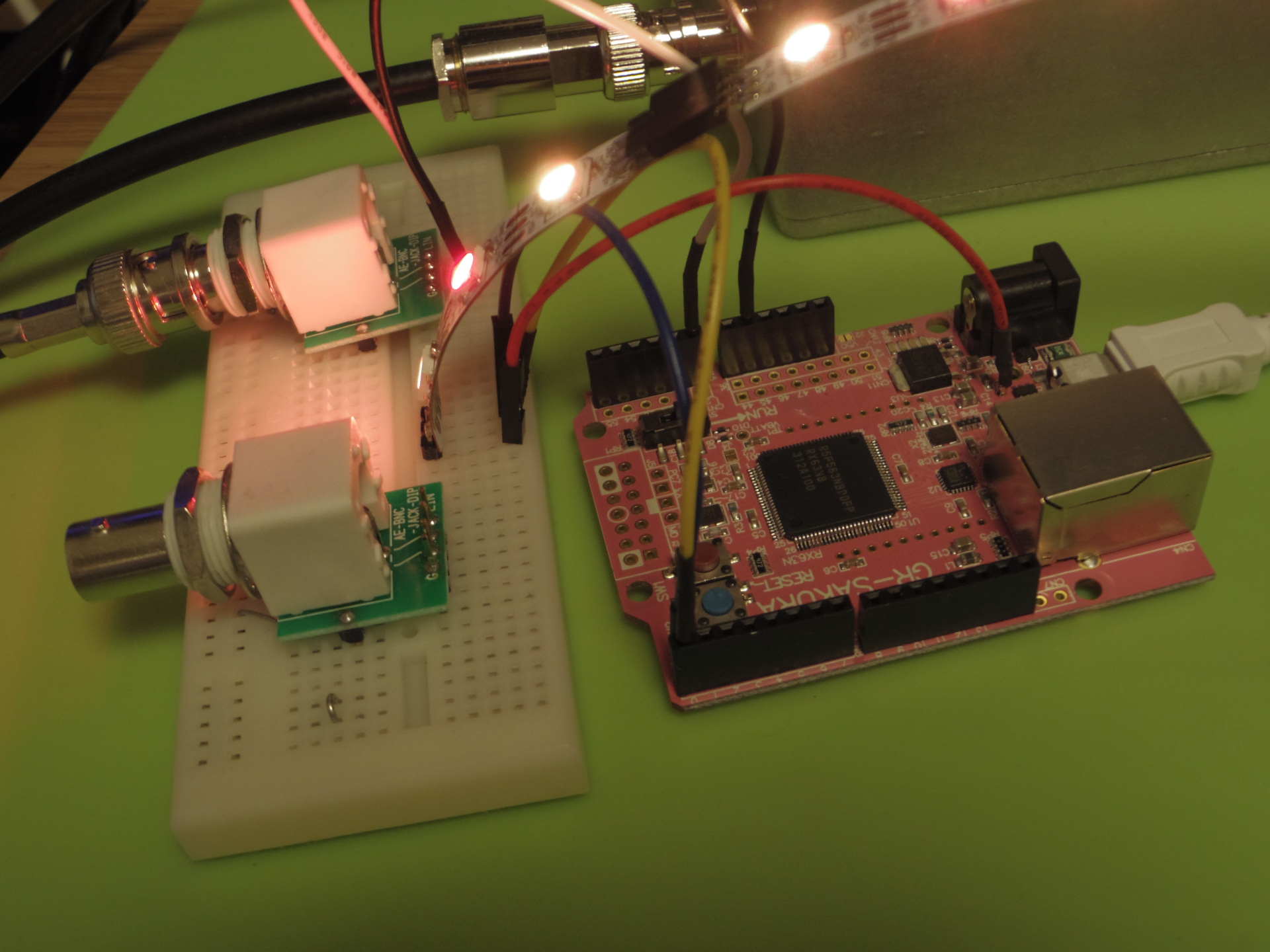
γ線分光計のγ線検出パルスのパルス電圧を、色相にマッピングして、時系列表示させるようにしてみた♫
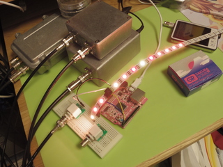 電流食うみたいで、容量のある電源でないと、動作が不安定になるようです。サンプルソースコードは、、、、
 電流食うみたいで、容量のある電源でないと、動作が不安定になるようです。サンプルソースコードは、、、、
-------
/*GR-SAKURA Sketch Template Version: V1.08*/
// GSR_2014_02
// (C) 2014, DIGI-P, BSD LICENSE for AS-IS.
//
#include <rxduino.h>
#include <iodefine_gcc63n.h>

#define INTERVAL 100
unsigned long loopCnt = 0;

#define SIZE_OF_CNT (0x1000)
unsigned long cnt[ SIZE_OF_CNT ];

unsigned short vPuls_curr = 0;
unsigned short vPuls_prv1 = 0;
unsigned short vPuls_prv2 = 0;
unsigned short vPuls_mark = 0;

long onLED0 = 0;
long onLED1 = 0;
long onLED2 = 0;
long onLED3 = 0;

void intrTimer(void);

const int waitHigh0 = 6;
const int waitLow0 = 13;
const int waitHigh1 =12;
const int waitLow1 = 10;
const int waitRet = 1000;

void code_0(void);
void code_1(void);
void code_ret(void);
void paint(void);
void color_phase(
    unsigned char *r,
    unsigned char *g,
    unsigned char *b,
    unsigned int phase  );

uint8_t p2podr;
uint8_t p21high;
uint8_t p21low;

unsigned char r[256];
unsigned char g[256];
unsigned char b[256];

unsigned char ptr = 0;
unsigned int timerCnt = 0;


void setup()
{
    int i;

    pinMode(PIN_LED0,OUTPUT);
    pinMode(PIN_LED1,OUTPUT);
    pinMode(PIN_LED2,OUTPUT);
    pinMode(PIN_LED3,OUTPUT);
    digitalWrite(PIN_LED0,0);
    digitalWrite(PIN_LED1,0);
    digitalWrite(PIN_LED2,0);
    digitalWrite(PIN_LED3,0);

    pinMode( A0, INPUT );

    for ( i=0; i<SIZE_OF_CNT; i++ ) {
        cnt[i] = 0;
    }
    loopCnt = 0;

    p2podr = PORT2.PODR.BYTE;
    p21high = p2podr | 0x02;
    p21low = p2podr & ~0x02;

    for( i=0; i<256; i++ ) {
        r[i] = 0x00;
        g[i] = 0x00;
        b[i] = 0x00;
    }
    pinMode( 0 ,OUTPUT);

    code_ret();


//    Serial.begin(38400, SCI_USB0 );
    analogReference(RAW12BIT);

//    timer_regist_userfunc( intrTimer );
}

void intrTimer(void)
{
    vPuls_curr = analogRead( A0 );

    if ((vPuls_prv1 > vPuls_prv2) && (vPuls_curr <= vPuls_prv1)) {
        vPuls_mark = vPuls_prv1;
        if ( cnt[vPuls_prv1] != 0xffffffff ) {
            cnt[vPuls_prv1]++;
        }
        if (vPuls_prv1 > 200) {
             onLED0 = 50;
        }
        if (vPuls_prv1 >= 1024) {
            onLED1 = 200;
        }
        if (vPuls_prv1 >= 2048) {
            onLED2 = 300;
        }
        if (vPuls_prv1 >= 3072) {
            onLED3 = 400;
        }
    }
    vPuls_prv2 = vPuls_prv1;
    vPuls_prv1 = vPuls_curr;
    loopCnt++;
}

void loop()
{
    int i;

    for( i=0; i<10000; i++ )
    {
        intrTimer();
        onLED0--;
        if (onLED0 < 0) {
            onLED0 = 0;
            digitalWrite( PIN_LED0, 0 );
        } else {
            digitalWrite( PIN_LED0, 1 );
        }
        onLED1--;
        if (onLED1 < 0) {
            onLED1 = 0;
            digitalWrite( PIN_LED1, 0 );
        } else {
            digitalWrite( PIN_LED1, 1 );
        }
        onLED2--;
        if (onLED2 < 0) {
            onLED2 = 0;
            digitalWrite( PIN_LED2, 0 );
        } else {
            digitalWrite( PIN_LED2, 1 );
        }
        onLED3--;
        if (onLED3 < 0) {
            onLED3 = 0;
            digitalWrite( PIN_LED3, 0 );
        } else {
            digitalWrite( PIN_LED3, 1 );
        }
        if ( vPuls_mark > 0 ) {
            if (vPuls_mark > 50) {
                color_phase( &(r[ptr]), &(g[ptr]), &(b[ptr]), vPuls_mark );
                ptr++;
            }
            vPuls_mark = 0;
            paint();
	}
    }
}

void code_0(void)
{
    int i;

    PORT2.PODR.BIT.B1 = 1;
    for ( i=0; i<waitHigh0; i++ ) {
        asm volatile ("nop\n");
    }
    PORT2.PODR.BIT.B1 = 0;
    for ( i=0; i<waitLow0; i++ ) asm volatile ("nop\n");
}

void code_1(void)
{
    int i;

    PORT2.PODR.BIT.B1 = 1;
    for ( i=0; i<waitHigh1; i++ ) {
       asm volatile ("nop\n");
    }
    PORT2.PODR.BIT.B1 = 0;
    for ( i=0; i<waitLow1; i++ ) asm volatile ("nop\n");
}

void code_ret(void)
{
    int i;
    for ( i=0; i<waitRet; i++ ) asm volatile ("nop\n");
}

void paint(void)
{
    int i;
    unsigned char cur;

    noInterrupts();
    for( i=0, cur=(ptr - 1); i<256; i++, cur-- ) {
        // Green
        if (g[cur] & 0x80) code_1(); else code_0();
        if (g[cur] & 0x40) code_1(); else code_0();
        if (g[cur] & 0x20) code_1(); else code_0();
        if (g[cur] & 0x20) code_1(); else code_0();
        if (g[cur] & 0x08) code_1(); else code_0();
        if (g[cur] & 0x04) code_1(); else code_0();
        if (g[cur] & 0x02) code_1(); else code_0();
        if (g[cur] & 0x01) code_1(); else code_0();
        // Red
        if (r[cur] & 0x80) code_1(); else code_0();
        if (r[cur] & 0x40) code_1(); else code_0();
        if (r[cur] & 0x20) code_1(); else code_0();
        if (r[cur] & 0x10) code_1(); else code_0();
        if (r[cur] & 0x08) code_1(); else code_0();
        if (r[cur] & 0x04) code_1(); else code_0();
        if (r[cur] & 0x02) code_1(); else code_0();
        if (r[cur] & 0x01) code_1(); else code_0();
        // Blue
        if (b[cur] & 0x80) code_1(); else code_0();
        if (b[cur] & 0x40) code_1(); else code_0();
        if (b[cur] & 0x20) code_1(); else code_0();
        if (b[cur] & 0x10) code_1(); else code_0();
        if (b[cur] & 0x08) code_1(); else code_0();
        if (b[cur] & 0x04) code_1(); else code_0();
        if (b[cur] & 0x02) code_1(); else code_0();
        if (b[cur] & 0x01) code_1(); else code_0();
    }
    code_ret();
    interrupts();
}


void color_phase(
    unsigned char *r,
    unsigned char *g,
    unsigned char *b,
    unsigned int phase  ) // 12bit
{
    unsigned int theta = phase & 0xfff;
    unsigned int offset = theta % 683;

    switch ( theta / 683 ) {
    case 0:
        *r = 0xff;
        *g = (offset * 255)/ 683;
        *b = 0x00;
        break;

    case 1:
        *r = ((683 - offset) * 255)/ 683;
        *g = 0xff;
        *b = 0x00;
        break;

    case 2:
        *r = 0x00;
        *g = 0xff;
        *b = (offset * 255)/ 683;
        break;

    case 3:
        *r = 0x00;
        *g = ((683 - offset) * 255)/ 683;
        *b = 0xff;
        break;

    case 4:
        *r = (offset * 255)/ 683;
        *g = 0x00;
        *b = 0xff;
        break;

    case 5:
    default:
        *r = 0xff;
        *g = 0x00;
        *b = ((683 - offset) * 255)/ 683;
    }
}
-------
まだ、ゴミコードとバグが残っているが、ご参考
トラックバック(0)
このブログ記事を参照しているブログ一覧: γ線分光計のフルカラーLEDリボン連携♪
このブログ記事に対するトラックバックURL: http://the.nerd.jp/blogs/cgi-bin/mt-tb.cgi/4899
リンク用バナ画像

Thank you for visitors:
from 7th, May. 2005
MY TWITTER
今月のイラスト/ムービー
応援サイト、その他

Visit RenderSan
<-- script type="text/javascript" src="http://swf.mikunavi.net/miku" width=150 height=44 --><-- /script --><-- br / -->

マイサイト